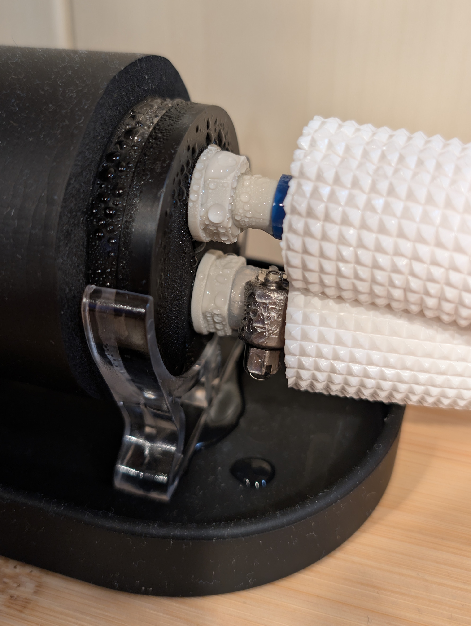
Condensation on reservoir fittings.

The dew point is the temperature at which moisture condenses out of the air, which is determined by absolute humidity and pressure.

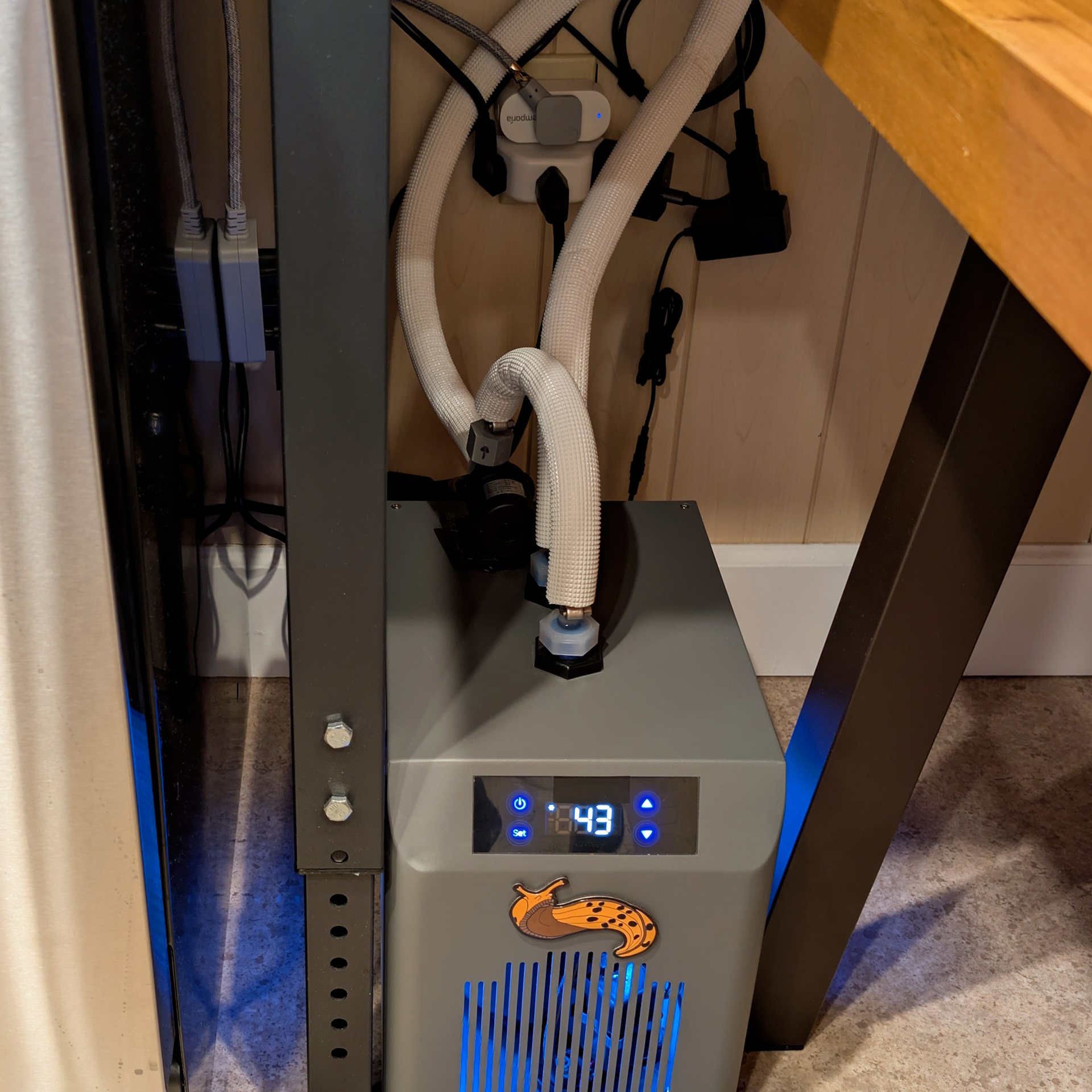
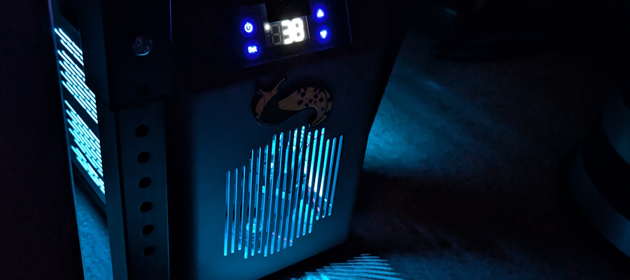
Water chiller with blue glow.

Terrarium Substrate Cooler

Concept

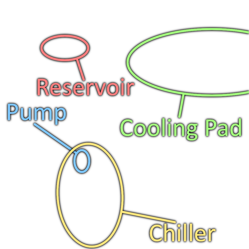
The use of an aquarium chiller to cool water that's pumped through a pad, which can be placed beneath an enclosure. This enables a wide range of cooling targets without directly impacting humidity, and creates a vertical thermal gradient similar to those found in nature — allowing residents to pick and choose their ideal temperature.

I developed this solution for Banana Slugs, which prefer temperatures of ~55°F (13°C). However, it's also useful for beating heatwaves, inducing diapause, and caring for certain species of Velvet Worms.

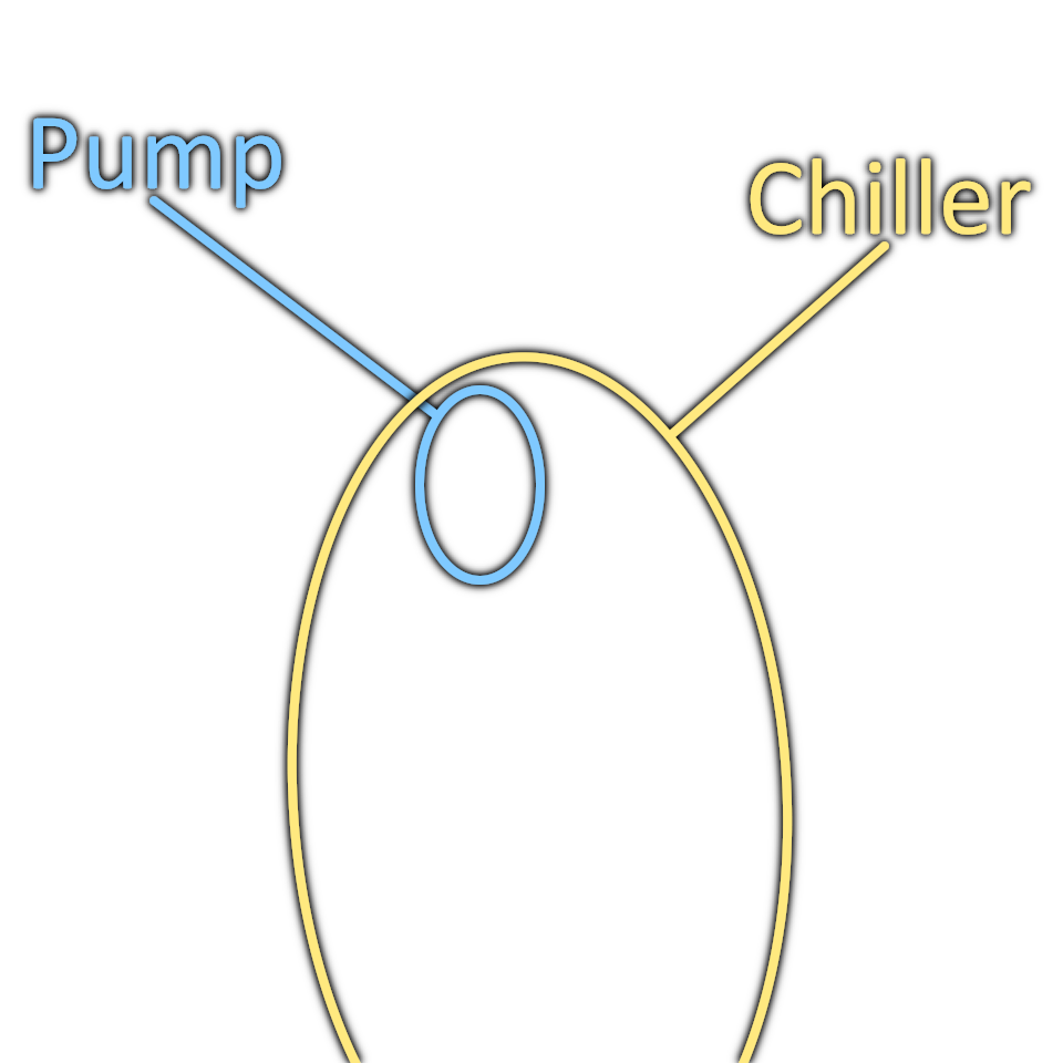
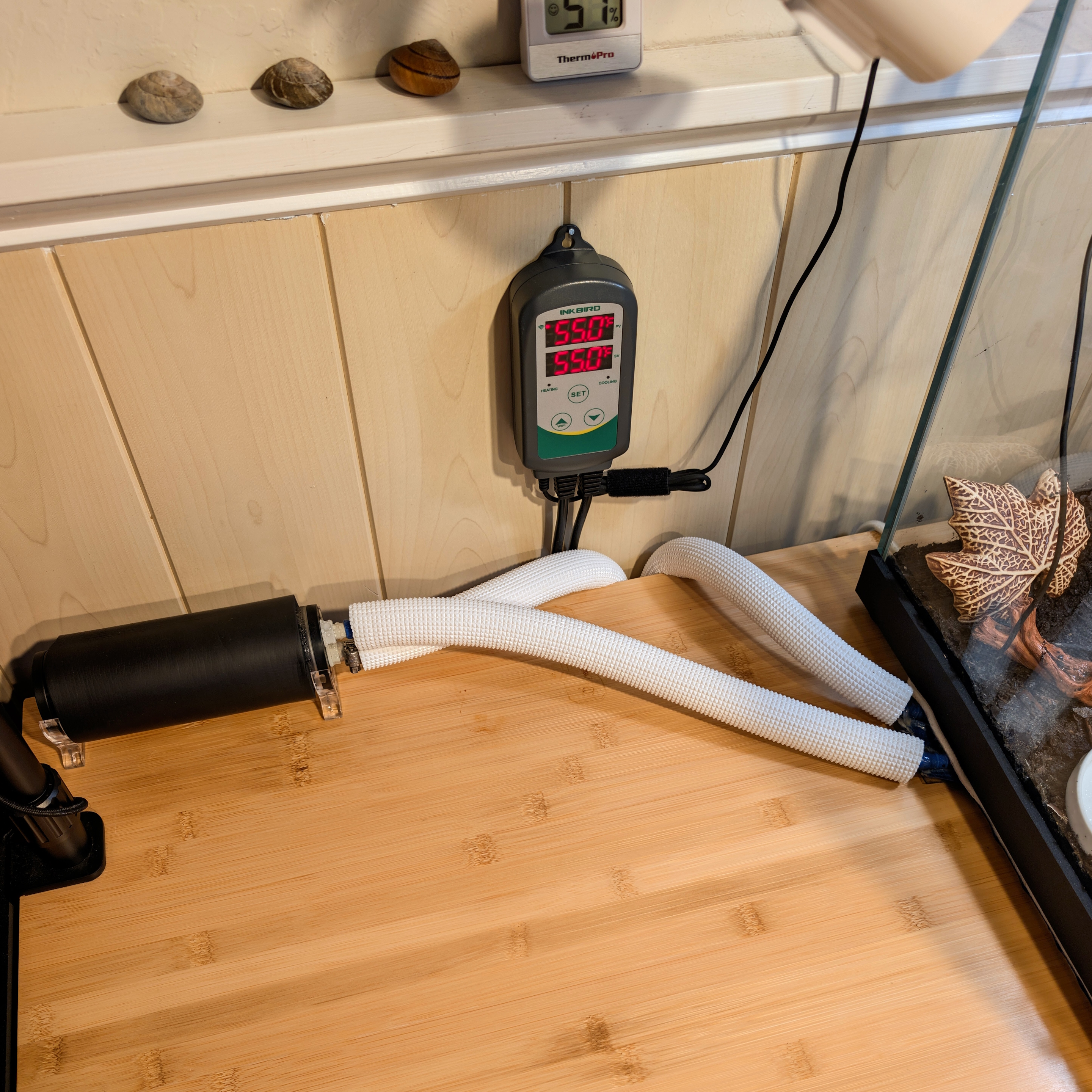
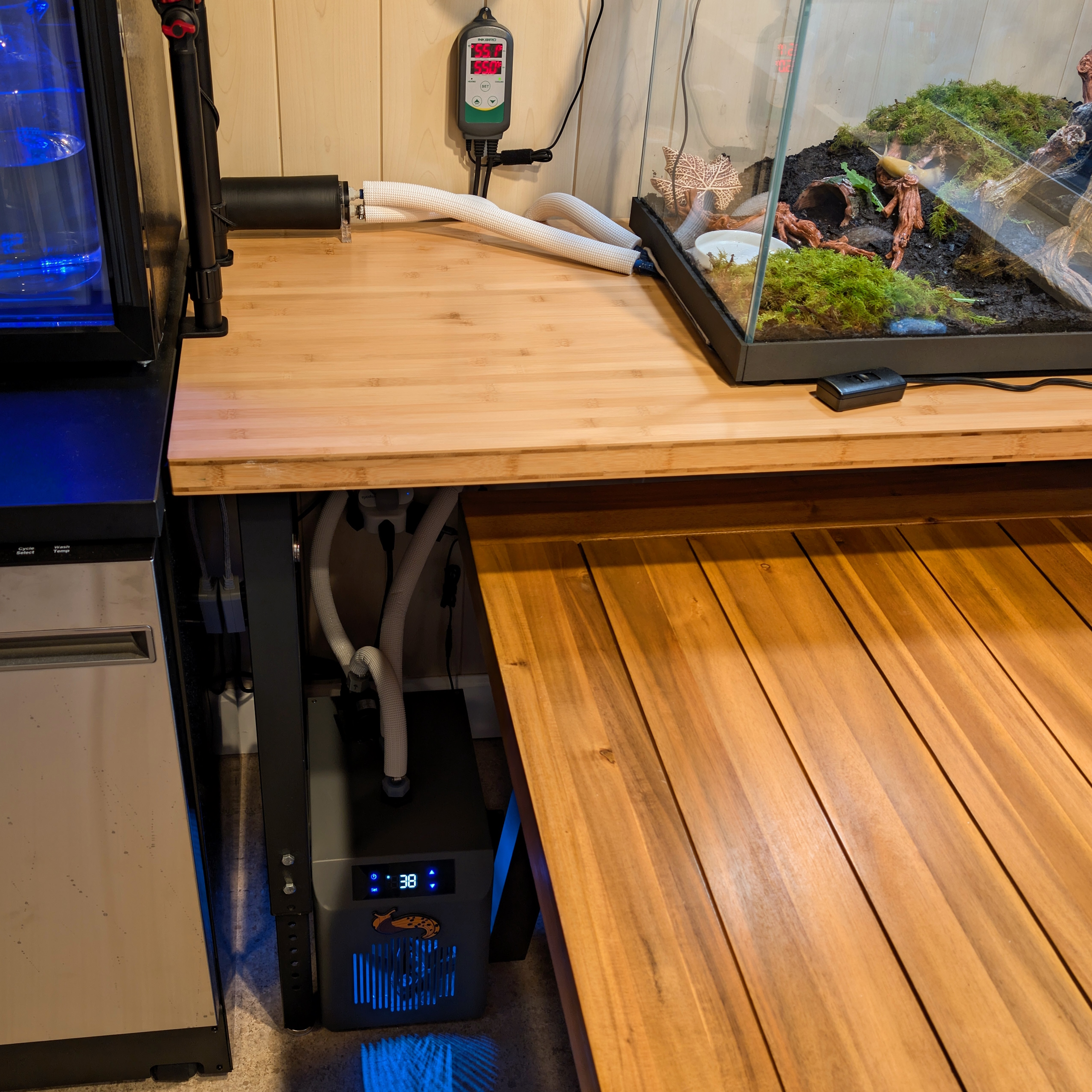
Tap pictures for annotation.
Prerequisites

  1. The flat base of your enclosure must sit flush against the surface it's set upon — there cannot be any trim pieces on the bottom edges keeping it elevated.
  2. The enclosure can only sit upon a solid surface — meaning no holes, slats, or gaps.
  3. Ensure adequate space for the reservoir at or above the enclosure's platform, and for the chiller to be lower than the reservoir. See dimensions below.
Width x Depth x Height
Reservoir 12 x 3 x 4" (30 x 8 x 10cm)
Chiller 12 x 16 x 18" (30 x 40 x 46cm)

Parts List

Prices Last Updated: July 18th, 2026

Minimum Parts

Substrate Thermometer 5.45
Aquarium Chiller 168.96
Chiller Fittings 8.39
Pad Fittings 3.49
Reservoir Fittings 7.99
Pump Fittings 9.59
Pump Power Supply 6.77
Coolant Pump 18.99 Failed after ~1yr of operation — consider keeping a spare.
Cooling Pad 57.99 Subtract 3" (8cm) from each of your enclosure's footprint dimensions to determine the largest pad that may be used. This ensures enough space for the risers to support the enclosure's weight.
Coolant Reservoir 17.59 Collects air trapped in the cooling loop.
Reservoir Cap 6.59 Seals the reservoir's fill port.
Reservoir Insulation 6.16 Improves thermal performance and limits condensation.
Tubing 7.99 Interconnects the loop's elements.
Tubing Insulation 15.99 Improves thermal performance and limits condensation.
Hose Clamps 5.79 Secures tubing to the barb fittings.
Rubber Risers 10.45 Creates a gap for the cooling pad beneath the enclosure.
1G Distilled Water 2.00 Coolant.
Total

Optional Upgrades

Silicone Mat 9.99 To protect the surface beneath the cooling pad from condensation if coolant drops below the dew point.
Silicone Tray 14.99 To protect the surface beneath the reservoir from condensation if coolant drops below the dew point.
Damper Pads 12.00 Affixing to the base of the pump reduces vibration noise.
Enclosure Insulation 13.99 To improve thermal performance. Install to any unobstructed surfaces on outside of the enclosure, at and below substrate height.
Substrate Heatsink 14.99 To greatly improve thermal performance by aiding vertical conductivity within substrate, which is also a must if incorporating a drainage layer. Select the largest "width" that the intended substrate depth can hide. Wash to remove machine oils, and place flat face atop the glass directly above cooling pad. Multiple are recommended for most footprints, spaced in parallel with their vertical faces ~4" (10cm) apart. Affix after placement with silicone sealant on only the lengthwise edges of each segment, so as to not insulate the glass/metal interface with either silicone or trapped air.
Basic Substrate Thermostat 18.99 Replaces the substrate thermometer, enabling thermal stability in highly variable ambients by controlling power to the pump and chiller. Ideally combined with the optional substrate heatsink, to shorten the lag between cooling commands and the result. Set the chiller thermostat's target to 34°F (1°C), and the substrate thermostat's differential to its lowest supported value.
Smart Substrate Thermostat 49.99 The same capability and notes as the Basic Substrate Thermostat described above. However, this also supports setting schedules (e.g., day/night and seasonal cycles), can alert to out-of-bound thermals, and charts thermal history.
Time-Delay Outlet 31.99 Protects the chiller from damage if utility power is briefly lost. Install between the outlet and chiller, or between the outlet and substrate thermostat if one's used.
Specialized Coolant 24.99 Coolant alternative, which contains biocide, limits bubbles, and lubricates the pump for a longer life. Up to two liters may be needed, depending on loop length.

Assembly

It's only about half as hard as it looks.

Required Tools

Slot Screwdriver To fasten hose clamps and reservoir cap.
14mm Wrench or Pliers To fasten G1/4 fittings.
Measuring Tape To measure for cuts.
Scissors To cut tubing and insulation.
Small Funnel To fill reservoir with coolant.
Towel To soak up any leaked coolant.

Instructions

Prep Chiller

  1. Chillers must be kept upright for at least 24 hours before any operation, which ensures that their compressor's oil has settled to a safe level. Failure to allow this time often results in compressor damage.
  2. Set aside the pump and tube fittings included with the chiller, as they're incompatible with this use case.
  3. Locate two separately-ordered chiller fittings, and place one of the chiller's included o-rings within each.
  4. Fasten these two prepped fittings to the top of the chiller.

Prep Cooling Pad

  1. With scrissors, cut the fitting off the end of the pad's tubing and discard the included insulation.
  2. Cut the pad's remaining tubing to 1" (25mm) lengths and discard the removed lengths.
  3. Press the small end of a pad fitting into each of the pad's tubes.

Prep Reservoir

  1. Ensure that the reservoir's black end pieces are fully-threaded to the acrylic glass, as they may have loosened during shipping.
  2. Identify the end with two holes and affix a reservoir fitting to each. Threads are tight, so double-check that the gaskets squash upon fastening.
  3. Affix the reservoir cap to the end with only one hole.

Prep Pump

  1. Set aside the pump's included fittings, as they aren't compatible with this use case.
  2. Affix the separately-ordered pump fittings and their included o-ring to each of the pump's ports.

Prep Tubing

  1. Place the chiller, cooling pad (plastic face upward), reservoir (oriented horizontally), and pump in your planned locations. The reservoir in particular must be at the loop's highest point, as its role is to collect trapped air while the coolant cycles.
  2. Cut four lengths of tubing — one between pad and reservoir, pad and chiller, chiller and pump, as well as the reservoir and pump. Lengths should have some slack.
  3. Sleeve the tubing's insulation such that all but ~1" (25mm) at each end of the tubes are fully covered. Fitment is tight, so long tubes may require sleeving multiple short lengths of insulation.

Install Tubing

  1. Use the now-insulated tubing to connect the pump's side fitting to one on the chiller, and the chiller's remaining fitting to one on the pad. Next, connect the pad to the fitting on the reservoir featuring an internal tube (visible through the acrylic), and then connect the reservoir's second fitting to the pump. These connections are made by pressing the tubing over the fittings' barbs until they're fully covered.
  2. Ensure that the reservoir can rotate such that the port connected to the pad is oriented above the one leading to the pump.
  3. Open the hose clamps by fully unscrewing them, and then affix to the tubing anywhere it covers a barb fitting.
  4. Take a break — this is about to get spicier.

Add Coolant

  1. Reassess fittings to confirm that they're sufficiently secure.
  2. Plug the pump's power supply into its planned outlet, and be ready to connect it to the pump.
  3. Remove reservoir cap and orient the reservoir such that its open port faces up and the tubes are downward, again ensuring that the reservoir is the loop's highest point.
  4. Loosely insert a funnel into the open port and add coolant until the reservoir is ~80% full.
  5. While maintaining reservoir orientation, connect the pump to its power supply.
  6. Coolant should drain from the reservoir, and there will be strange noises as the pump struggles with air pockets. Keep adding coolant to the reservoir and try to maintain a coolant level of at least 80%.
    • If coolant struggles to flow despite maintaining level in the reservoir, this is because of large air pockets trapped in the loop. Manipulate the tubing until the pockets pass through the system, especially by vertically aligning the tube running between the pump and reservoir. The tubes can go back to the intended positions once the filling process is complete.
  7. Once the coolant's flow sounds steady and the reservoir maintains at least an 80% coolant level on its own, ensure that this remains the case for at least 2 consecutive minutes.
  8. Reaffix the reservoir's cap and set it back in its planned location.
  9. Disconnect the pump from power.
  10. The loop is now under pressure, so over the next 5 minutes, inspect fittings for leaks and tighten anything suspect.

Add Reservoir Insulation

  1. Cut the reservoir insulation to a length of 5.5" (14cm).
  2. Sleeve insulation over the reservoir until the coolant is no longer visible.
  3. Find the reservoir's clear plastic feet and affix them to the black end caps.
  4. Set the reservoir back down, and rotate it such that the port leading to the pad is oriented above the port leading to the pump.

Position Cooling Pad

  1. Move cooling pad aside and set the enclosure in its planned location.
  2. Place a rubber riser beneath each of the enclosure's four corners, and an additional beneath perimeter spans exceeding ~12" (30cm) — as long as placement won't block sliding of the pad in the following step.
  3. Lift one side of the enclosure, and slide only the cooling pad (not the tubes) beneath it.
  4. Set the enclosure back down and ensure that each of the risers is taking some of the enclosure's weight. The pad should be compressed against the glass but not taking all of the enclosure's weight.
  5. Power the pump back up.

Populate Enclosure

  1. Add substrate if you haven't already, and keep in mind that depth is a factor in temperature deltas. A height gradient will create a thermal gradient, which may or may not be desireable.
  2. Install thermometer with its probe above the cooling pad on the substrate's surface.

Configure Chiller

  1. Power the chiller on and set its thermostat differential to 4°F (2°C).
  2. Set a coolant temperature based on deltas in the following section on Performance.
  3. Take a break for ~6 hours to allow the enclosure's thermals to settle.

Tune System

  1. Reassess fittings for leaks and tighten anything suspect. Some condensation is normal if coolant drops below the dew point.
  2. Begin adjusting the coolant's temperature to reach the desired substrate temperature, and allow ~2 hours before reassessing these adjustments.

Troubleshooting

No Cooling Despite Chiller Continually Running

Likely caused by a lack of coolant flow due to an unpowered or failed pump, pinched tube, or large air pocket in the coolant line.

Adding More Coolant To The Loop

More coolant may need to be added to the loop in the event of a leak, or if a large air pocket was dislodged — which would be evident by a trickling sound emanating from the reservoir. To open the loop for filling:

  1. Ensure that the pump is running so that the pad doesn't deflate, which would cause coolant to erupt upon opening the reservoir.
  2. Orient the reservoir vertically, such as when it was originally filled, and then open the cap.
  3. Loosely insert a funnel into the reservoir, and add coolant until the level is at least 80%.
  4. Reseal the reservoir and set it back down.

Disconnecting The Loop

If the coolant loop needs to be taken apart, such as for servicing parts:

  1. Ensure that both the pump and chiller are turned off.
  2. Place the reservoir into a container that can hold fluid.
  3. Slowly loosen the reservoir's cap until it's fully removed and fluid stops draining. This is to equalize the loop's pressure, which will make the messes from further servicing much more manageable.
  4. Move the container to beneath your planned disconnection, and proceed with unfastening.

To refill the loop once reconnected, follow the steps in the original instructions under Add Coolant.

Substrate Thermostat: Thermal Overshoot

If utilizing a substrate thermostat, it is normal for the substrate temperature to somewhat overshoot above and below its set target, which is due to the substrate's conductivity causing a delay between cooling commands and the result. However, overshoot can be minimized in the following ways:

  1. Use a trick for setting a 0° cooling differential with the smart thermostat: Create a new automation scene in the "Smart" menu, and set the "If" condition to some near point in the future — while using "Then" to set your cooling differential to 0°. Delete the scene after it has been triggered.
  2. Incorporate a substrate heatsink to improve conductivity, as described under Optional Upgrades.
  3. Raise the substrate's moisture content to improve conductivity.
  4. Make the substrate shallower to improve conductivity.
  5. Adjust the coolant thermostat to a higher temperature. This, however, equates to lower performance, impacting how far the substrate can be cooled below ambient. Such a drawback may not be a problem for some use cases.

Additional Help

If you've run into a strange problem or would like feedback on a special use case, feel free to reach out. My means of contact can be found on the site's Main Page.

Performance

Based upon the "Minimum Parts" list.

Observation Conditions

Ambient 72°F (22°C)
Substrate Target 55°F (13°C)
Substrate Material 1" (25mm) Topsoil
Enclosure Material 5/16" (8mm) Glass
Enclosure Footprint 24 x 18" (60 x 45cm)

Water to Substrate Deltas

Wet Soil 7°F (4°C)
Dry Soil 15°F (8°C)

A delta is the difference between two values, which in this case compares the water temperature with that of the substrate's surface. The smaller the delta, the more efficient the cooling.

Power Draw

Idle 7W
48°F (9°C) Water 145W (30% Duty)
40°F (3°C) Water 145W (90% Duty)